Last but not least, for registering the screen I used the amazing “active presenter: software, which free version is really incredible!
So, as a start, for the moment (March 2016) the mesh gradient is still a developing function in Inkscape. I search on the net details and I found how to activate it (it is not implict activated in version 0.91). More, from the site:
http://wiki.inkscape.org/wiki/index.php/Mesh_Gradients
I fond some more things, like the lack (for the moment) of functionalities as UNDO or DELETE mesh line. Other things (like the short-cuts) was not working for me… maybe the content there is only a wish list…
OK, but lets start with it.
1 Technical issues
1.1 Activate the function. See:
http://goinkscape.com/how-to-unlock-the ... -inkscape/
1.2 Type:
1.2.1 Diamond: NODES (Corner, margin or “inside”)
1.2.2 Circle: Bezier handles
1.3 Erik discovered issues
1.3.1 Mesh lines can be added only from one mesh margin to the opposite one. It is not possible to draw a mesh from a margin to an adjacent margin.
1.3.2 There is not possible to intersect 2 interior mesh lines that are connecting same opposite margins. Practically, all interior mesh lines are “parallel” with 2 margins, and between them.
1.4 How to collect colour for a node
1.4.1 Select the node
1.4.2 Select pick colours from image tool (F7)
1.4.3 Click desired colour
1.5 Add a mesh line: in “mesh” mode, move the mouse until you are over an existing mesh line. The cursor will lokk like the mesh cursor with a supplementary “+”. Double click and a new mesh line will be drawn “perpendicular” on the line you clicked.
2 Erik tips and tricks
2.1 Don't use the round mesh - it is a square rounded and it not close at 360 so you cannot smooth colour at the 0-360 degrees line.
2.2 Especially when there are a lot of nodes, identifying their handles is not an easy task. Sometimes, after introducing new mesh lines or moving nodes, their handles are far away from the nodes. “S” shapes can appear.
2.3 Avoid “S” shapes of the lines, that can appear because of strange placement of the handles – strange borders can appear. Example:
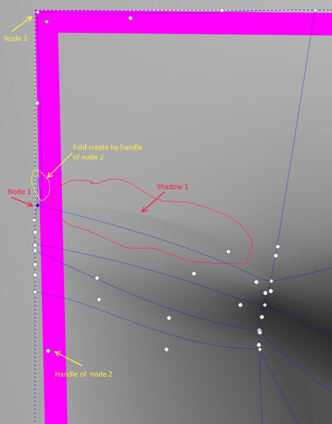
- ex1.jpg (43.83 KiB) Viewed 3205 times
2.4 Arrange / align handles when you have a lot of nodes. If you have 4 mesh lines (except the margin) a new mesh perpendicular on them will create 4+2=6 new nodes and 4x4 + 2x3 = 22 new handles
2.5 Moving
2.5.1 A handle – is moving individual
2.5.2 A node – when you move a node, all his handles are moving (2 for corner node, 3 for margin node, 4 for interior node).
2.5.3
3 Drawing issues
3.1 Identify the colour zones. They can mainly be:
3.1.1 Round zones. They will have allocated a “colour pole” - mesh lines will cross in the “centre” of the zone. Example:
https://www.youtube.com/watch?v=CSJkw5x ... V8&index=4
3.1.2 Linear zones. Those will have allocated a “colour mesh line”, through the “middle” of the zone. Example:
https://www.youtube.com/watch?v=7lXynSv ... V8&index=3
3.1.3 Mixed zones. Use your phantasy and experience.
3.1.3.1 Half moon. Example:
https://www.youtube.com/watch?v=8Wom0P1 ... V8&index=2
3.1.3.2 S linear shadow
https://www.youtube.com/watch?v=ZMfcoGs ... V8&index=5
3.1.3.3 Triangle shadow – borders that remains visible are because of a bug – the alpha channel of the background is not 1, don't know why…
https://www.youtube.com/watch?v=mzaENWW ... V8&index=1
3.1.4 Strong borders – with clear different coloured on “left” and “right”. This situation can be treated in 2 ways:
3.1.4.1 Create 2 areas that have as border the “strong border”.
3.1.4.2 Consider 2 linear zones close to the border and you will drag the handles very close to one of the mesh line.
3.2 Sketching the mesh lines position. For this, create first an extra layer on which we will draw simple lines, on the position where we estimate the mesh lines will be.
3.2.1 Mark the colour poles on the extra layer (use a pencil)
3.2.2 Mark colour mesh lines on the extra layer (use a pencil)
3.2.3 Try to optimise the lines, by including the poles on the lines
3.3 Splitting
Splitting an area in several areas or objects is necessary to reduce the number of mesh gradients. For drawing – tracing a photo – the following steps are required:
3.3.1 Split the drawing in “objects” (layers).
3.3.1.1 Parts of the drawing that are over-posing each-other shall be different objects (on different layers). Ex: mouth, nose, eye and face of a person. They can later further split (nose in nose and nostrils, etc)
3.3.1.2 After splitting on objects, choose the priority / level of each object (the order of the layers)
3.3.2 Split the objects on areas (same layer). Example: split the face in 3 areas (forefront / middle / chin). Areas of an object shall be adjacent. In the adjacent areas “un-fitting” borders can appear. See later how to deal with them.
3.3.3 As examples, see
https://www.youtube.com/watch?v=0EQV2Ci ... V8&index=6
and
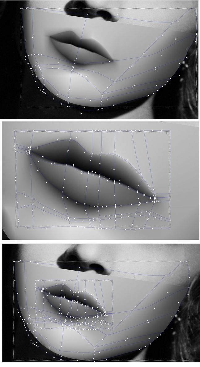
- Ex3.jpg (90.91 KiB) Viewed 3205 times
3.3.4 To remove a discontinuity in colour, add another mesh line
3.3.5 To remove strong borders between 2 zones, “prolong” mesh lines from “zone 1” in “zone 2” and the select only for the margin mesh nodes in zone 2, the colour corresponding to the equivalent nodes in zone 1. Example:
https://www.youtube.com/watch?v=0EQV2Ci ... V8&index=6
3.3.6 Where it is a discontinuity between a zone colour and the colour below it, add mesh lines in those points (“perpendicular” to the discontinuity) and then deal only with the margin nodes (that are in the areas of “discontinuity). See examples
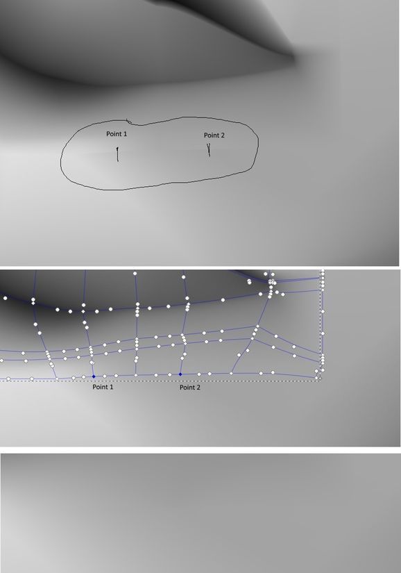
- Ex 2.jpg (31.56 KiB) Viewed 3205 times