Vertical stroke diameter instead of right angle diameter

Post questions on how to use or achieve an effect in Inkscape.
toxigames
Posts: 149
Joined: Sat Aug 17, 2013 7:28 pm

Vertical stroke diameter instead of right angle diameter

Postby toxigames » Fri Oct 02, 2015 10:57 pm

I have run into an issue where I need to have vertical stroke diameters set to the same vertical diameter size everywhere on the stroke. Normally stroke diameters is the right angle diameter on any location on the stroke and this is constant. But what I want is to have the vertical diameter to be constant, and the right angle diameter to be flexible.

On the image below I show what I mean. The two objects strokes don't match when the objects paths are not horizontal. The more the difference in angle on the two the worse the issue becomes.

I want to do what a calligraph tool does with an angle of 90, only with strokes instead...

Is it possible to somehow set stroke width to become based on vertical diameter instead?

Image


Using the calligraph tool with an angle of 90. I need to do this with strokes instead.
Image

User avatar
brynn
Posts: 10309
Joined: Wed Sep 26, 2007 4:34 pm
Location: western USA
Contact:

Re: Vertical stroke diameter instead of right angle diameter

Postby brynn » Sat Oct 03, 2015 9:27 am

That doesn't exist in Inkscape, as far as I know. What is the use case where you need to do this? I mean, do you just need a couple of objects like this, or do you want to draw a whole large image with that kind of effect?

What happens when the line gets vertical? Does the stroke completely disappear?

toxigames
Posts: 149
Joined: Sat Aug 17, 2013 7:28 pm

Re: Vertical stroke diameter instead of right angle diameter

Postby toxigames » Sat Oct 03, 2015 6:09 pm

brynn wrote:That doesn't exist in Inkscape, as far as I know. What is the use case where you need to do this? I mean, do you just need a couple of objects like this, or do you want to draw a whole large image with that kind of effect?

What happens when the line gets vertical? Does the stroke completely disappear?


It's for a car game, images of sloped platforms of 256px wide. I'm going to have hundreds of pieces like this. In the game I place the images side by side to form a consistent image of the ground the player drives on. If the vertical "diameter" (don't know what else to call it) were the same I would be able to mix and match almost any ground piece with each other. But because it isn't the slopes that are to angled to much won't match with slopes that are not (just as in my example image).

And yes an inherent effect of what I want is that if the line gets completely vertical the stroke would completely disappear and that's okay.

I found out that I could get the effect by using a combination of Stroke to Path and then Pattern along Path extension with parameters ribbon, repeated, 0px space. However it's a tedious process and prone to sometimes crash due to the number of objects that have to be repeated along the path(the objects have to be really thin, like 2px each else the "stroke" result is to uneven). The image below is created this way and the result is what I want.

Image

v1nce
Posts: 696
Joined: Wed Jan 13, 2010 4:36 am

Re: Vertical stroke diameter instead of right angle diameter

Postby v1nce » Mon Oct 05, 2015 7:29 am

What's wrong with the calligraphy tool ?

Lazur
Posts: 4717
Joined: Tue Jun 14, 2016 10:38 am

Re: Vertical stroke diameter instead of right angle diameter

Postby Lazur » Tue Oct 06, 2015 9:09 am

Did you try using transforms and set them preserved in the prefs (Shift+Ctl+P)?
Sounds odd but theoretically possible:
  • set transformations preserved from optimised
  • draw an infinite wide object on canvas
  • group it (Ctrl+G)
  • scale the group's width to ~~0
  • enter the group, and draw your lines; preferably delete original object.

Adding a transformation matrix may also work via the xml editor (Shift+Ctrl+X), but maybe it will trigger rendering issues somewhere.

For filled paths instead of the pattern along path extension I'd also try the motion.

toxigames
Posts: 149
Joined: Sat Aug 17, 2013 7:28 pm

Re: Vertical stroke diameter instead of right angle diameter

Postby toxigames » Wed Oct 07, 2015 8:59 pm

Lazur URH wrote:Did you try using transforms and set them preserved in the prefs (Shift+Ctl+P)?
Sounds odd but theoretically possible:
  • set transformations preserved from optimised
  • draw an infinite wide object on canvas
  • group it (Ctrl+G)
  • scale the group's width to ~~0
  • enter the group, and draw your lines; preferably delete original object.

Adding a transformation matrix may also work via the xml editor (Shift+Ctrl+X), but maybe it will trigger rendering issues somewhere.

For filled paths instead of the pattern along path extension I'd also try the motion.


Thank you for the suggestion, however I couldn't make that work, got some weird stuff happen.

toxigames
Posts: 149
Joined: Sat Aug 17, 2013 7:28 pm

Re: Vertical stroke diameter instead of right angle diameter

Postby toxigames » Wed Oct 07, 2015 9:01 pm

v1nce wrote:What's wrong with the calligraphy tool ?


It's much to hard to control for the purpose that I have described. Thickness of the "stroke" with the calligraphy tool will be too wide or too thin at some places, especially in the ends and would require a lot of manual edits to correct.

User avatar
bartovan
Posts: 191
Joined: Sun Feb 09, 2014 4:14 am
Location: Belgium
Contact:

Re: Vertical stroke diameter instead of right angle diameter

Postby bartovan » Wed Oct 07, 2015 9:19 pm

You can do something based on the following idea. Let's say you want your "vertical stroke width" to be 10px.
- draw a curved line with bézier tool :tool_pen:
- duplicate it (Ctrl+D)
- move the duplicate up 10px (you can use eg. Object > Transform, or set the arrow step to 10px in Edit > Preferences > Behavior > Steps)
These two lines will have a consistent "vertical stroke width" of 10px.
Capture.PNG
Capture.PNG (18.46 KiB) Viewed 2593 times


To make them into one object:
- select both curves with :tool_selector:
- activate node tool :tool_node:
- select two left end nodes and join them with "join selected endnodes with a new segment"
- do the same for the two right end nodes
Portfolio bartovan.com
Tumblr / Instagram / Pinterest / Facebook / Twitter / OpenClipArt
Shop at Society6 / RedBubble
Using latest stable Inkscape on Ubuntu (current stable release) and Win 7.

toxigames
Posts: 149
Joined: Sat Aug 17, 2013 7:28 pm

Re: Vertical stroke diameter instead of right angle diameter

Postby toxigames » Wed Oct 07, 2015 11:01 pm

bartovan wrote:You can do something based on the following idea. Let's say you want your "vertical stroke width" to be 10px.
- draw a curved line with bézier tool :tool_pen:
- duplicate it (Ctrl+D)
- move the duplicate up 10px (you can use eg. Object > Transform, or set the arrow step to 10px in Edit > Preferences > Behavior > Steps)
These two lines will have a consistent "vertical stroke width" of 10px.
Capture.PNG


To make them into one object:
- select both curves with :tool_selector:
- activate node tool :tool_node:
- select two left end nodes and join them with "join selected endnodes with a new segment"
- do the same for the two right end nodes


Thank you for the suggestion! I wish this would work though, but it seems you are only partly right. It only works right in the middle of the stroke, that is only for the actual path, which is in reality a line with no width. Measured right in the middle of the path the vertical width, from the first stroke to the second, is indeed the same everywhere with your method. But it doesn't work for the 'breadth' of the stroke though. The thicker the stroke and the bigger the angle difference the worse the offset becomes. As shown in the image below you can see the difference in my current solution (using Stroke to Path and Pattern along Path with ribbon effect) and your suggestion (duplicating and offsetting the path):

Image

User avatar
brynn
Posts: 10309
Joined: Wed Sep 26, 2007 4:34 pm
Location: western USA
Contact:

Re: Vertical stroke diameter instead of right angle diameter

Postby brynn » Thu Oct 08, 2015 3:11 am

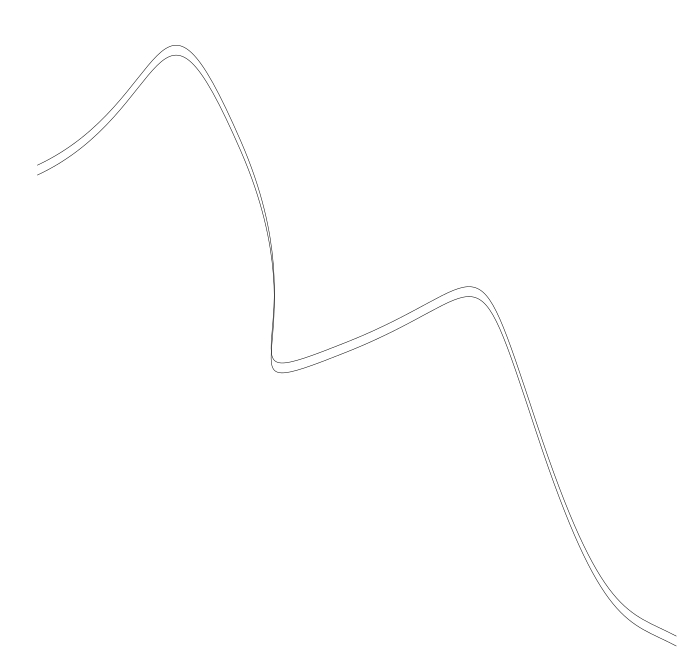
So you want both the stroke and the filled object to behave the same way -- 0 width at vertical, some defined width at horizontal? In that case, you'll have to create something like a custom stroke, which is really just another filled object. You'll have to duplicate the path from the right side of the filled object, to be used as the left path of the stroke object. Duplicate again, to create the right side. Essentially....well, literally, you'll use duplicates of the same path, for the whole thing.

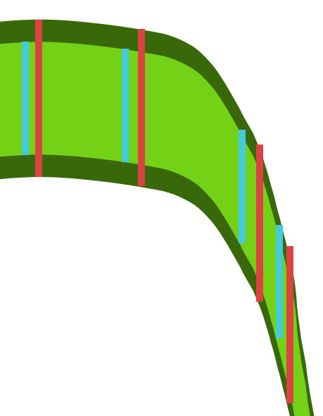
So let's say you need a fill object (the light green part in your examples) with a dark green stroke on either side.

1 -- draw the path you need
2 -- duplicate
3 -- move it up or down by whatever amount you want for the "stroke" object
4 -- duplicate, but don't move
5 -- duplicate
6 -- move it up or down by whatever amount you want for the "fill" object
7 -- duplicate, but don't move
8 -- duplicate
9 -- move it up or down by whatever amount you want for the "stroke" object
10 -- now go back to the 1st path and the 1st duplicate and select both bottom nodes
11 -- click "Join selected endnodes with a new segment" button on the Node tool control bar
12 -- do the same at the top end
13 -- repeat for the other 2

Edit
PS -- Brilliant solution, bartovan!! I can't take credit for that. Just giving instructions based on his idea :D

v1nce
Posts: 696
Joined: Wed Jan 13, 2010 4:36 am

Re: Vertical stroke diameter instead of right angle diameter

Postby v1nce » Thu Oct 08, 2015 4:29 am

fixed.jpg
fixed.jpg (26.98 KiB) Viewed 2539 times
Or just use the calligraphy tool

1 -- draw the path you need (with height = internal height) ; make sure ther's no stroke ; set the fill color as waht you want for "internal" color
2 -- duplicate
3 -- move it down by whatever amount you want for the "stroke" object
4 -- duplicate, but don't move
4 - change fill color for what you want for border color
5 -- duplicate
6 -- move it up by 2X whatever amount you want for the "stroke" object
7 -- select your last 2 copies
8 -- merge them = path / union (ctrl + + )
9 -- lower the selected object (page down)

voila.

Lazur
Posts: 4717
Joined: Tue Jun 14, 2016 10:38 am

Re: Vertical stroke diameter instead of right angle diameter

Postby Lazur » Thu Oct 08, 2015 6:05 am

toxigames wrote:
Lazur URH wrote:Did you try using transforms and set them preserved in the prefs (Shift+Ctl+P)?
Sounds odd but theoretically possible:
  • set transformations preserved from optimised
  • draw an infinite wide object on canvas
  • group it (Ctrl+G)
  • scale the group's width to ~~0
  • enter the group, and draw your lines; preferably delete original object.

Adding a transformation matrix may also work via the xml editor (Shift+Ctrl+X), but maybe it will trigger rendering issues somewhere.

For filled paths instead of the pattern along path extension I'd also try the motion.


Thank you for the suggestion, however I couldn't make that work, got some weird stuff happen.


Yes there seems to be some rendering issues but it can work.

Transformed with scale(5e-4,1) parameters.
Stroke width indication is messed up, and some parts are chopped, but those issues can be worked out.


ttst1.png
ttst1.png (128.02 KiB) Viewed 2529 times


ttst1.svg
(6.34 KiB) Downloaded 191 times

toxigames
Posts: 149
Joined: Sat Aug 17, 2013 7:28 pm

Re: Vertical stroke diameter instead of right angle diameter

Postby toxigames » Thu Oct 08, 2015 8:02 am

Oh wow some interesting methods and instructions you guys give here! I will certainly try those out tomorrow.

Thanks again

User avatar
brynn
Posts: 10309
Joined: Wed Sep 26, 2007 4:34 pm
Location: western USA
Contact:

Re: Vertical stroke diameter instead of right angle diameter

Postby brynn » Thu Oct 08, 2015 8:07 am

v1nce wrote:Or just use the calligraphy tool

1 -- draw the path you need (with height = internal height) ; make sure ther's no stroke ; set the fill color as waht you want for "internal" color
2 -- duplicate
3 -- move it down by whatever amount you want for the "stroke" object
4 -- duplicate, but don't move
4 - change fill color for what you want for border color
5 -- duplicate
6 -- move it up by 2X whatever amount you want for the "stroke" object
7 -- select your last 2 copies
8 -- merge them = path / union (ctrl + + )
9 -- lower the selected object (page down)

voila.


v1nce, which settings for Calligraphy tool do you use? Isn't it still hard to control with Calligraphy tool?

User avatar
brynn
Posts: 10309
Joined: Wed Sep 26, 2007 4:34 pm
Location: western USA
Contact:

Re: Vertical stroke diameter instead of right angle diameter

Postby brynn » Thu Oct 08, 2015 8:12 am

Did you say why you need this kind of effect? Just curious :D

v1nce
Posts: 696
Joined: Wed Jan 13, 2010 4:36 am

Re: Vertical stroke diameter instead of right angle diameter

Postby v1nce » Thu Oct 08, 2015 10:28 am

brynn wrote:
v1nce wrote:Or just use the calligraphy tool

1 -- draw the path you need (with height = internal height) ; make sure ther's no stroke ; set the fill color as waht you want for "internal" color
2 -- duplicate
3 -- move it down by whatever amount you want for the "stroke" object
4 -- duplicate, but don't move
4 - change fill color for what you want for border color
5 -- duplicate
6 -- move it up by 2X whatever amount you want for the "stroke" object
7 -- select your last 2 copies
8 -- merge them = path / union (ctrl + + )
9 -- lower the selected object (page down)

voila.


v1nce, which settings for Calligraphy tool do you use? Isn't it still hard to control with Calligraphy tool?

Same settings as shown in #1


Return to “Help with using Inkscape”